After Hurricane Ivan tore through Pensacola. I quickly
discovered that I really need a bigger compressor than the little one
that I had. It just didn't handle 35's. Okay it really couldn't
handle 31's. A few nails in the tires convinced me. I always
had my eye on the York compressors, and after reading a few of the trials
and tribulations of others trying to find them out of the junkyard and
mate them up, I decided that it was much simpler to just buy the whole
kit from Kilby.
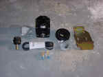
| Installation: |
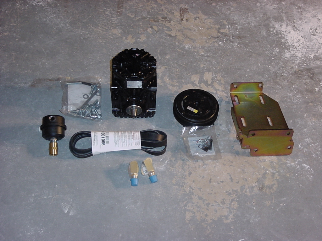
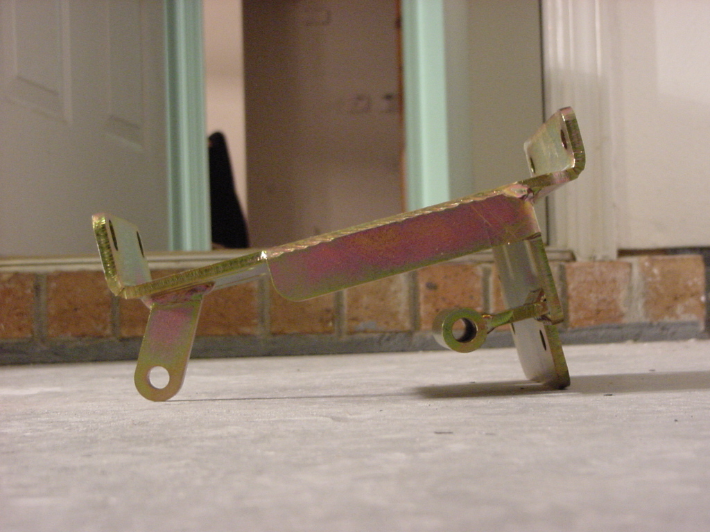
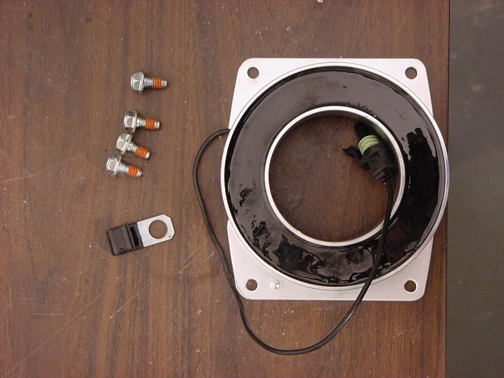
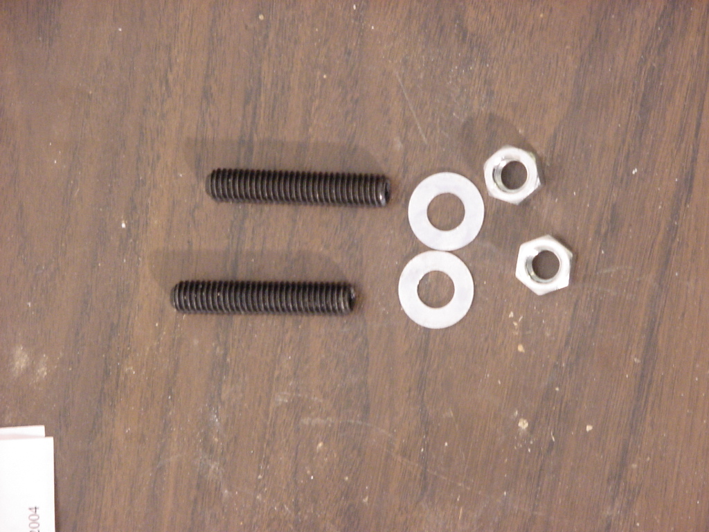
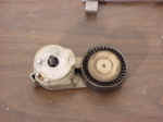
Here
is what comes in the kit. |
 |
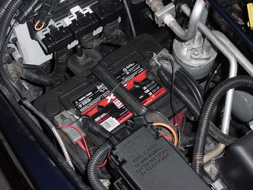
1. Disconnect the Battery. A 13mm wrench works on the battery
bolts. |
|
|
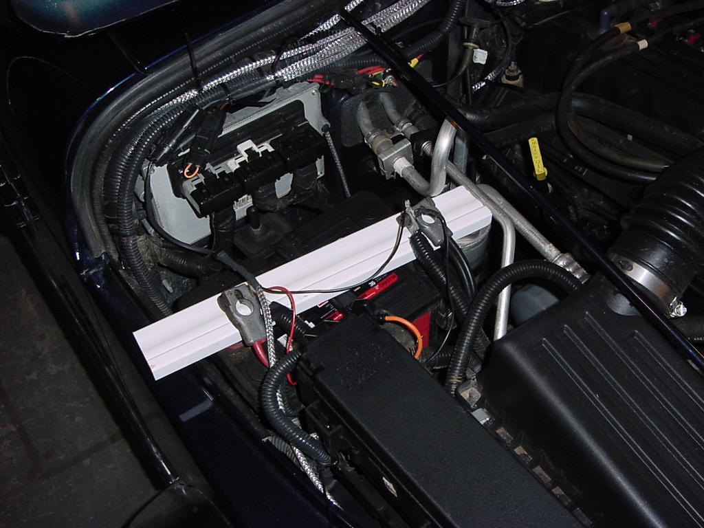
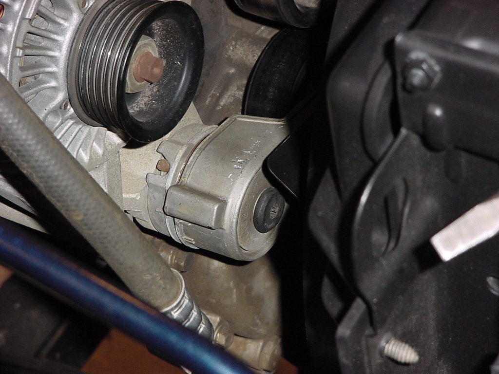
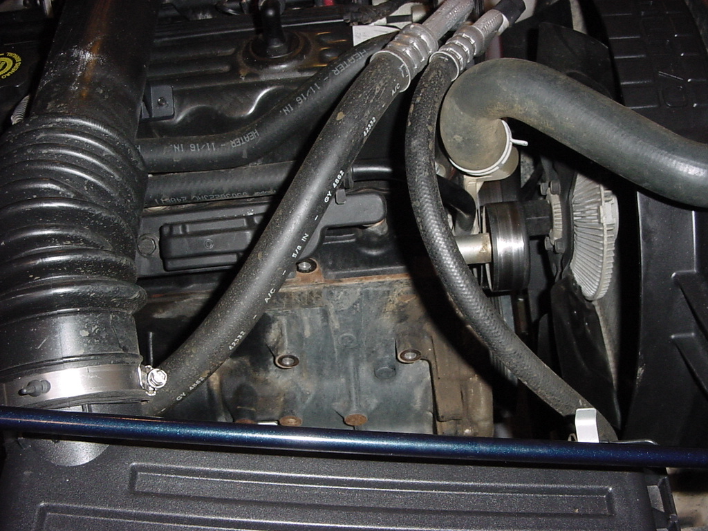
| 2. Remove the factory serpentine belt. You will need to just grab
the end of the tensioner with a big pair of pliers. A channel
lock pliers work well. Just slide the belt off of one of the
pulley's and feed it around everything. |
|
|
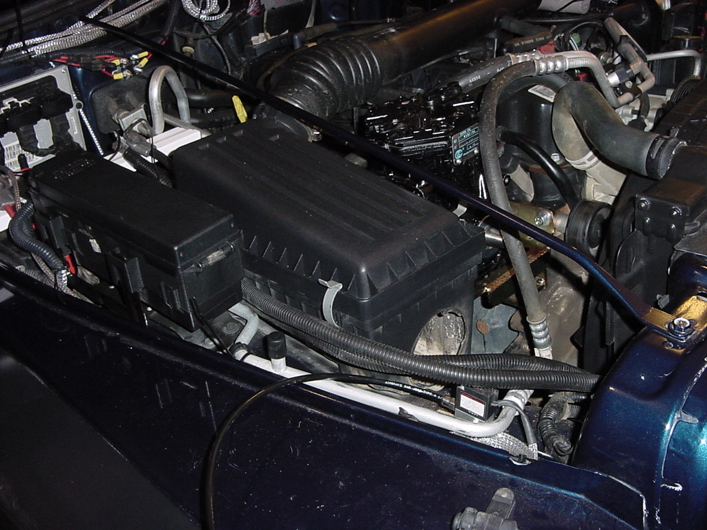
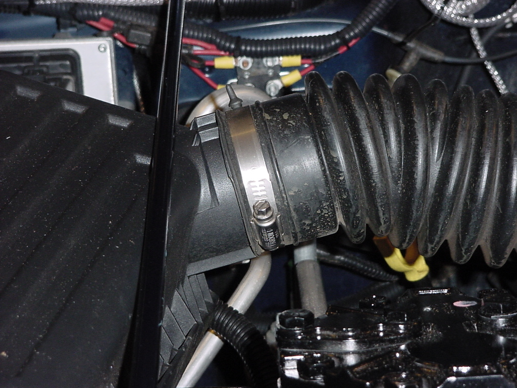
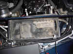
| 3. Remove the stock Air Box to give you more room to work around in this
area. I first tried just removing the horn to work on everything,
but found that the box kept getting in the way. First loosen
the clamp holding the inlet hose to the air box, and pull the hose
off of the box. Then unclip the cover and remove it and the
filter. |
|
|
| 4. Remove the 3 bolts holding the Air Box to the fender. There
are 3 nuts on the underside. You will need an 8mm socket and
an extension for the bolts and a 10mm combo wrench for the nuts.
Be careful with these nuts, the can fall into the bump stop cup and
are a pain to fish out. |
 |
 |
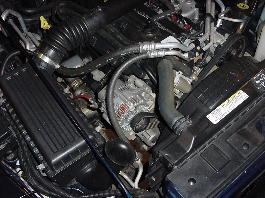
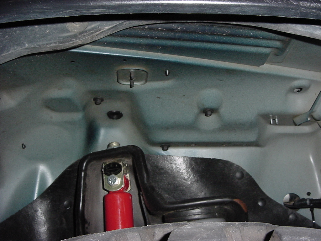
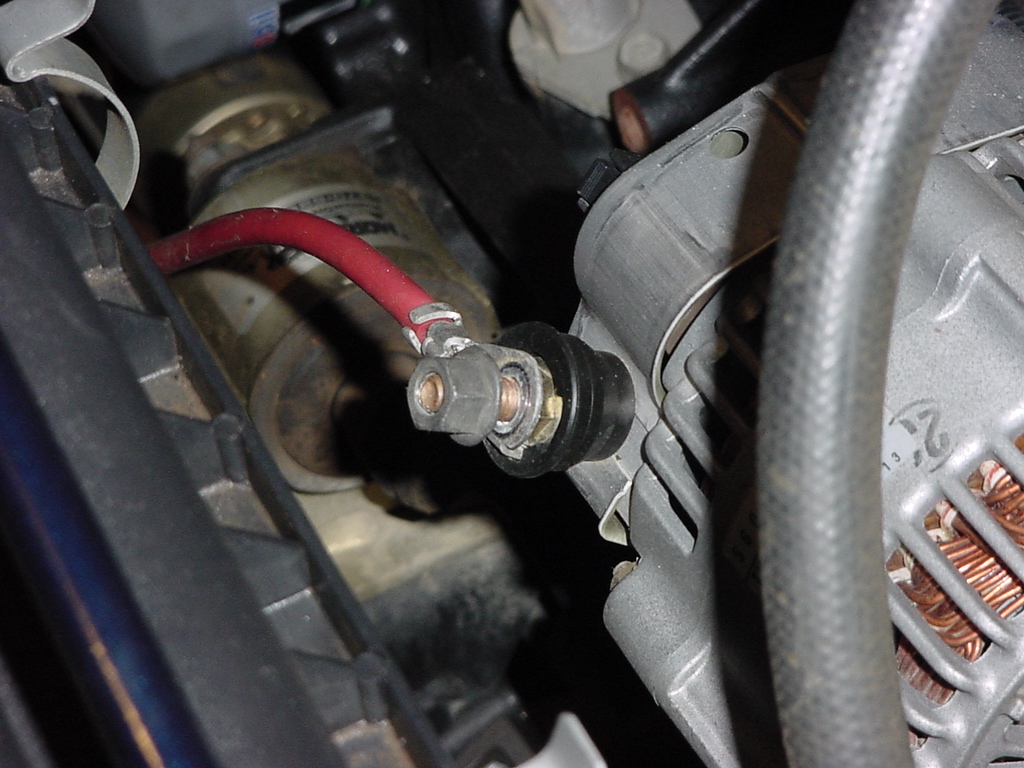
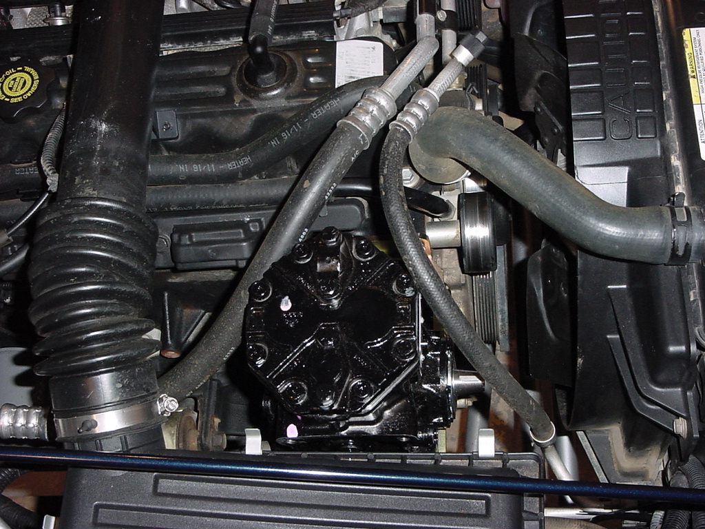
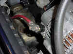
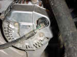
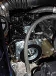
| 5. Now remove the Alternator. First disconnect the positive wire
from the alternator. You will need a 10mm Combo Wrench. Hold onto the wire when you loosen
the nut, you do not want to turn the fitting. |
 |
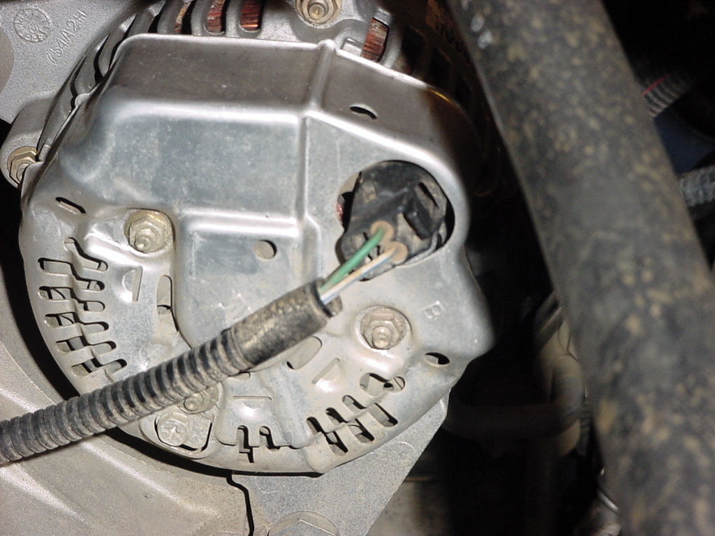
| 6. Remove the plug from the back of the alternator. There is also
a small push retainer on the side of the alternator bracket that you
will need to remove, don't worry, you won't reuse it. |
 |
 |
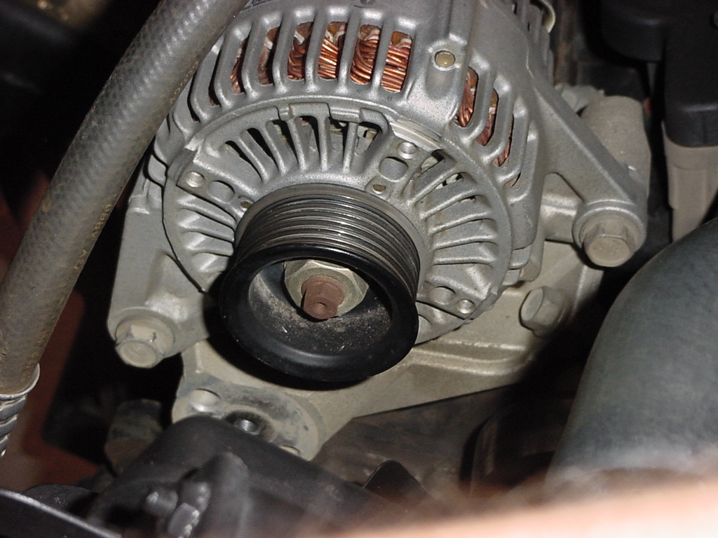
| 7. Remove the alternator by first removing the 2 bolts that hold the
alternator to the bracket. You will need a 15mm combo wrench
and a 15mm socket. These bolts are in pretty tight. I
found another part that the Jeep Gorilla installed. |
 |
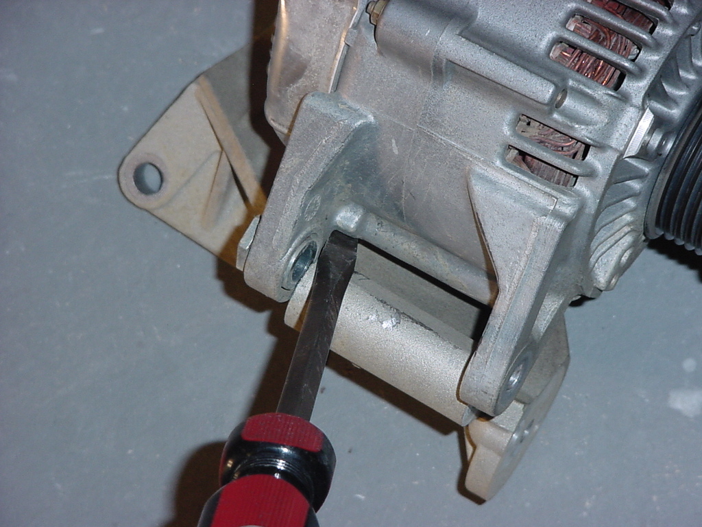
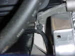
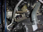
| 8. Once you have the bolts removed you will need to pull the
alternator out. It may not want to come out, you can take a
flat tip screwdriver and pry up on the bottom edge to separate the
alternator from the bracket. As you can see with the air box
there is not a lot of room. |
 |
 |
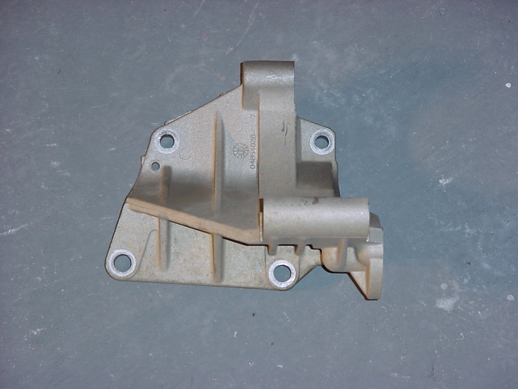
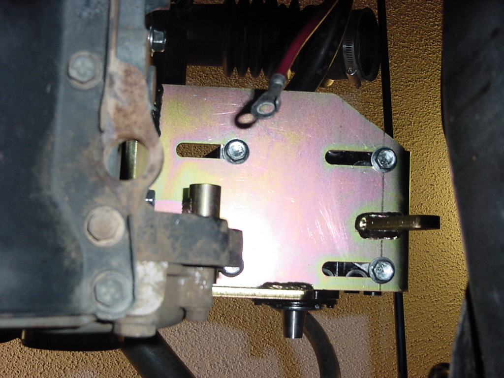
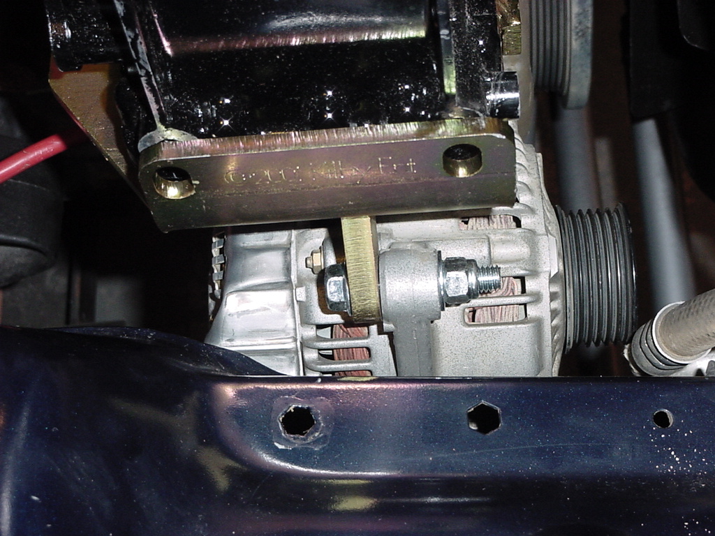
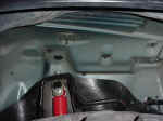
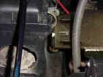
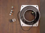
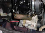
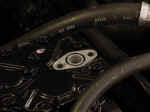
| 9. Now remove the Alternator bracket from the engine. You will
need a 9/16" Combo wrench and a 9/16" Socket and extension
(to get the one underneath) or you can lay under the jeep and reach
up to get the bottom bolts. Here is a good shot showing the
4 holes for the bolts. |
 |
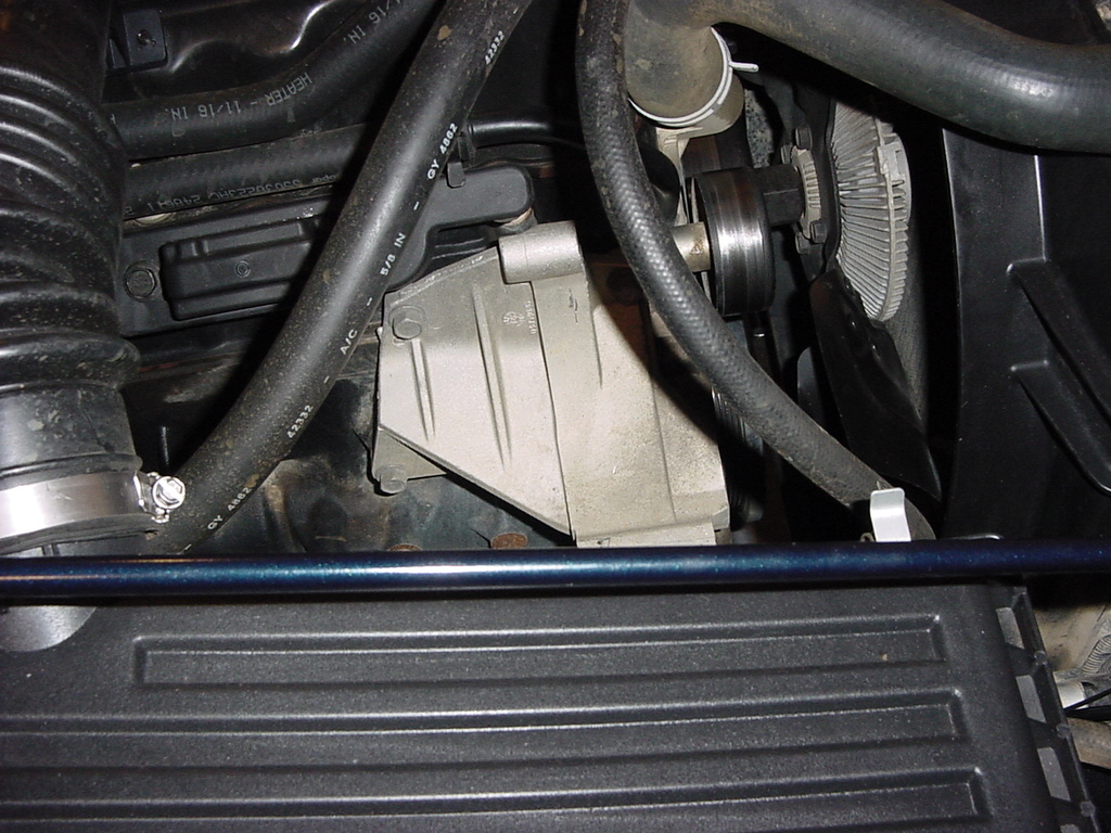
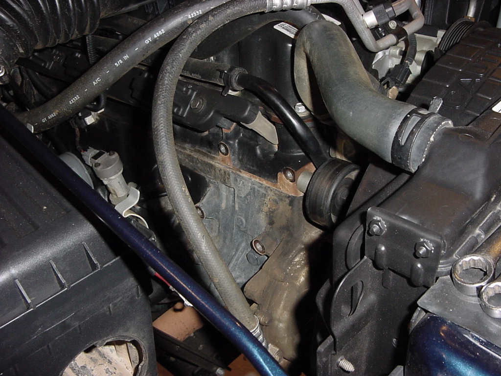
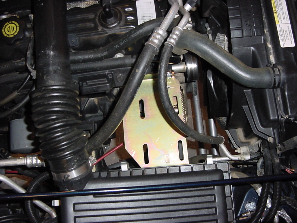
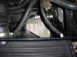
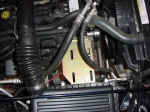
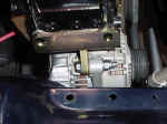
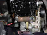
| 10. Take the chance to clean up where the bracket was mounted, once the
Kilby's goes in there isn't a lot of room to work in here. As
you can see still not very much room with the air box in, this is
the reason why you needed to remove it earlier. |
 |
 |
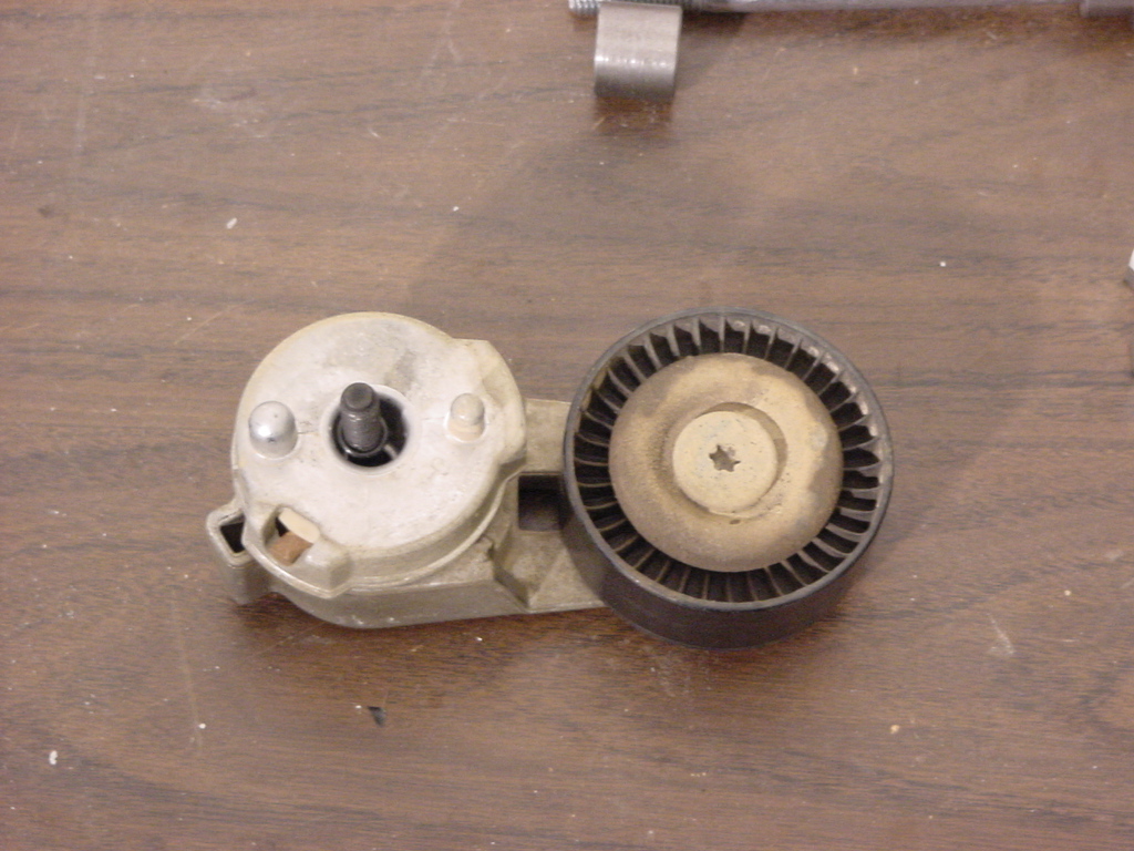
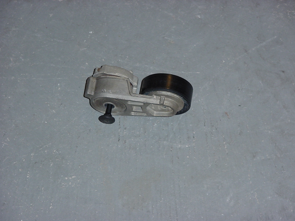
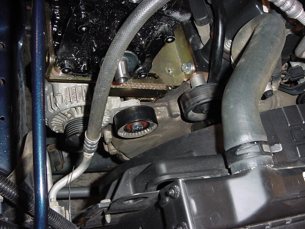
| 11. Remove the OEM tensioner pulley from the tensioner. You will
need a T-40 Torx. If you need to remove the tensioner from the
bracket so that you can put it in a vise that bolt is also a T-40.
Mine was on really tight so I needed to. |
 |
 |
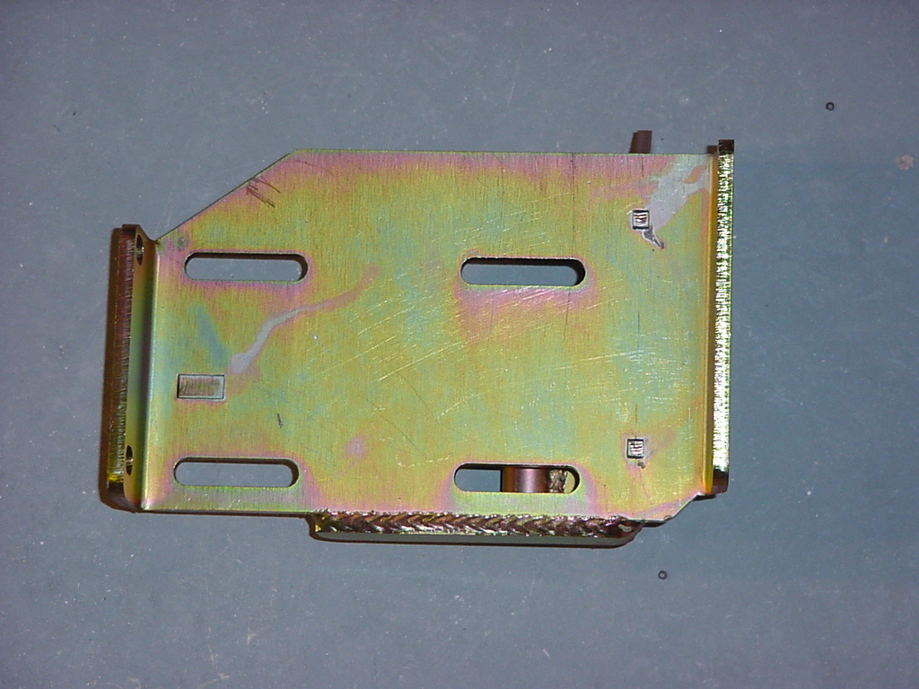
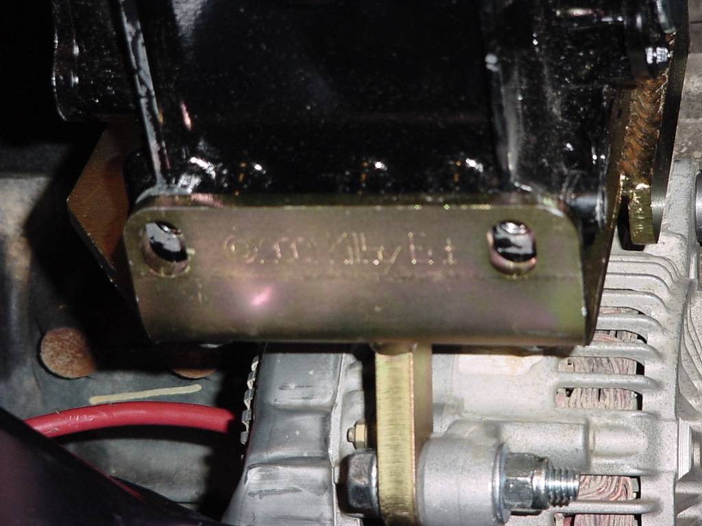
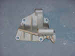
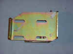
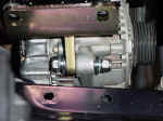
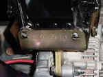
| 12. Find the kilby's bracket and test fit it into position.
Mount it into the factory position using (4) 3/18-16x1" bolts
and flat washers. Start all the bolts by hand, then tighten
to factory specs. |
 |
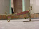 |
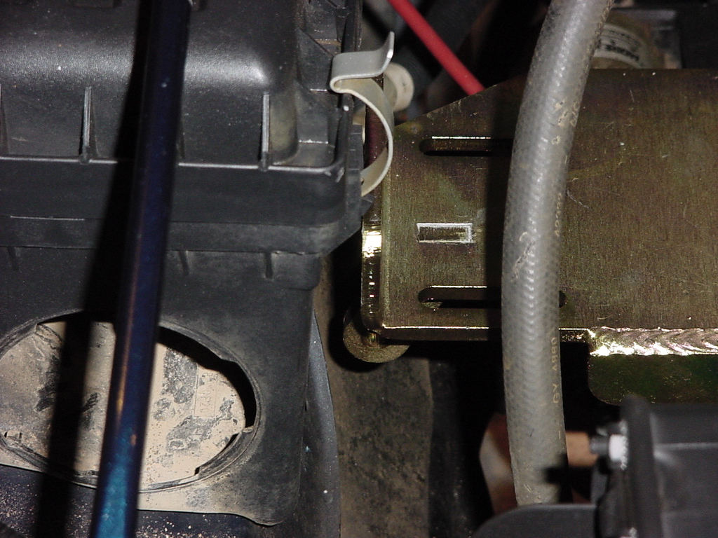
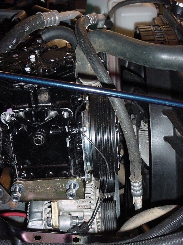
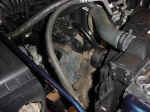
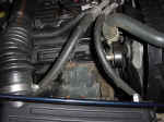
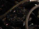
| 13. Here is a couple shots of how much room you would have to work with
if the factory air box was still installed. |
 |
 |
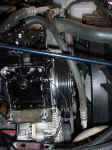
| 14. Now place the York Compressor on to the bracket and install (4) 3/8-16x1.5"
bolts and flat washers. Tighten until just finger tight then
back off 1/2-1 turn, you will need to slide the compressor around
when you install the belt. These bolts need a 9/16" Socket.
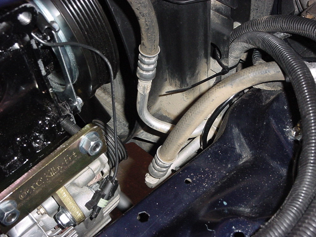
You will notice that if you have A/C that the lines will rub on the
compressor, you will need to carefully bend the aluminum hard pipes
to clear the lines away from the compressor. Be careful that
you don't kink the lines. |
|
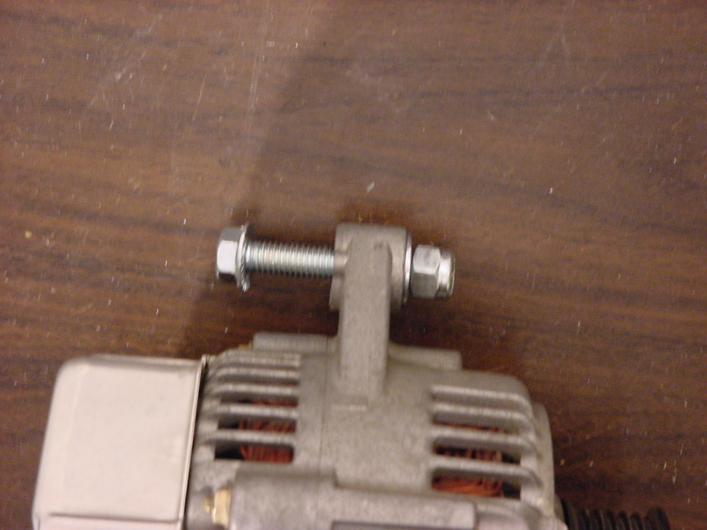
|
| 15.
Position the alternator below the bracket and bolt it to the single
ear on the bracket with the remaining 3/8-16x2" bolt, flat washers,
and Nylock nut. Do not tighten. |
 |
 |
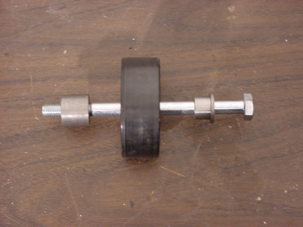
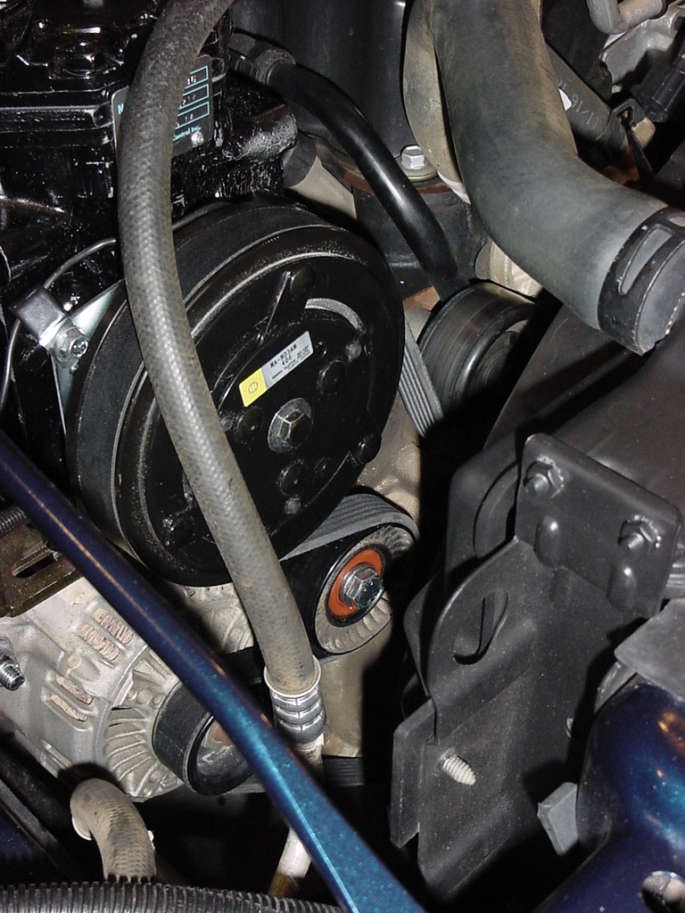
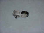
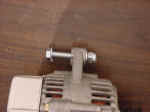
| 16. Insert the M10-140mm bolt through the M10 Idler bushing, then the
OEM Idler pulley, then the M10x3/4" idler spacer. |
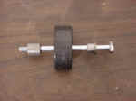 |
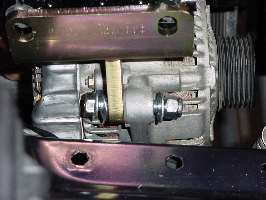
| 17. Insert the idler assembly through the first alternator mounting foot,
through the welded sleeve, then into the second mounting foot of the
alternator. You may need to rotate the fan blades to get it
to fit. Tighten both bolts. A 9/16" socket and 9/16"
Combo wrench for the single leg, and 11/16" Combo Wrench for
the idler pulley. |
 |
 |
| 18.
This is about the point that I looked back at the compressor and realized
that Kilby's didn't mention installing the clutch assembly onto the
compressor. Hmm I really didn't feel like taking the
compressor back out, so I just installed the parts in place. |
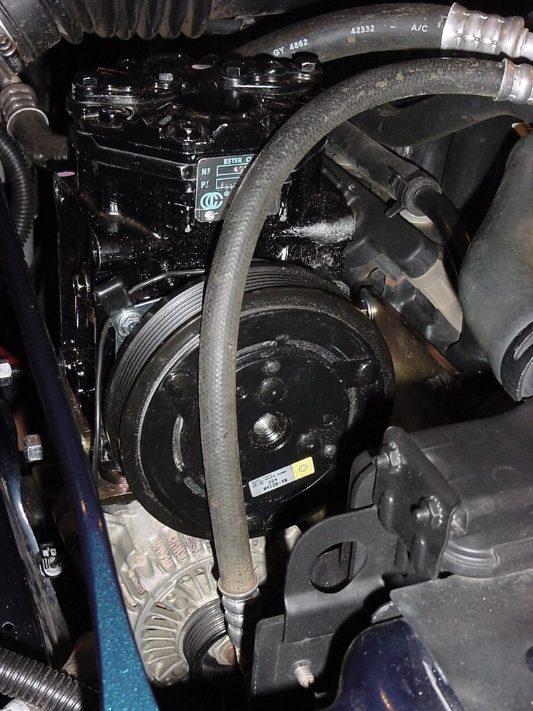
| 19.
Install the magnetic clutch onto the compressor housing. I decided
to install the clutch with the wire on top, so that I could see it.
I put the clamp in the upper outer bolt hole. Thread the 4 bolts
into the housing then tighten with a 3/8" Socket. |
 |
 |
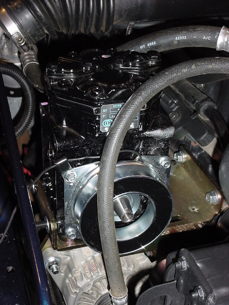
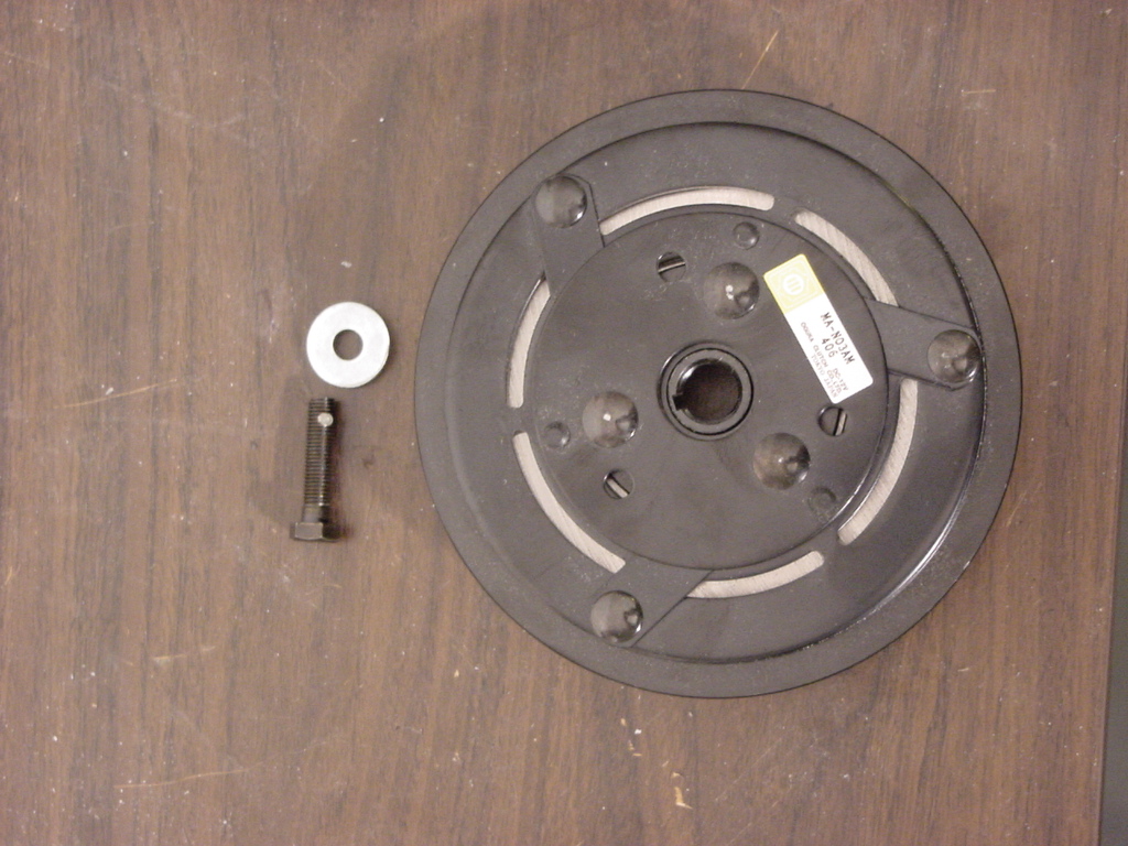
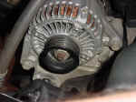
| 20. No install the pulley onto the shaft. Slide the Pulley over the clutch,
you may need to pull back on the A/C line a little to get it under
it. Then insert the washer onto the bolt and thread the bolt
into the shaft. You will need a 1/2" socket to tighten
the bolt. |
|
|
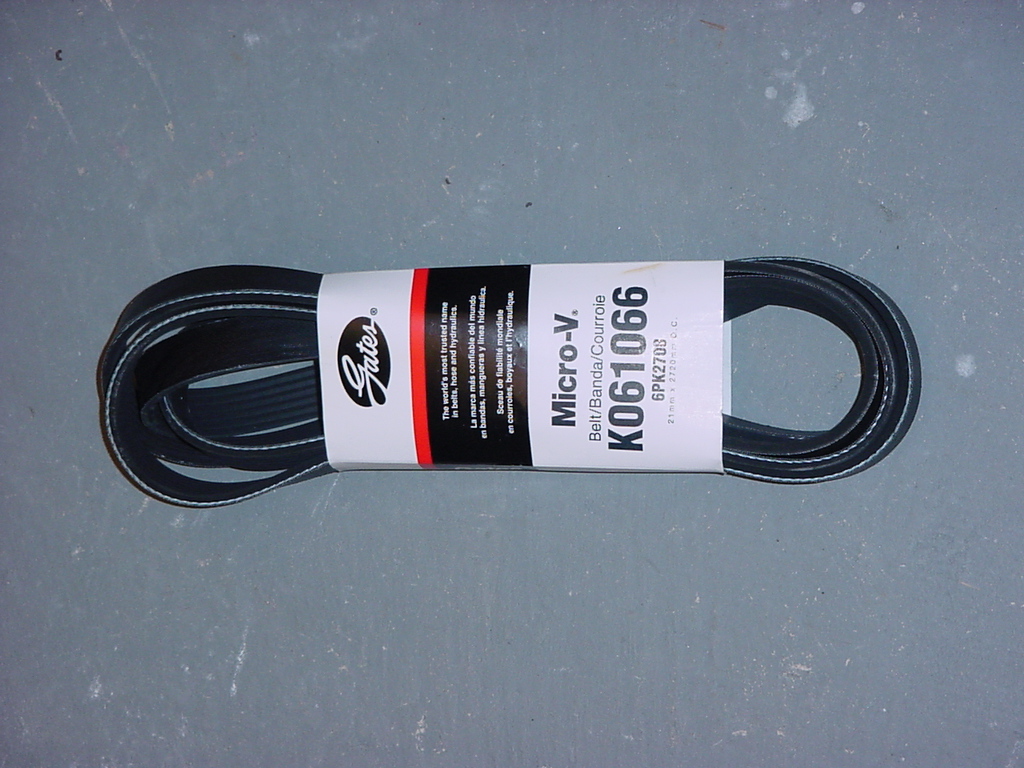
| 21.
Install new serpentine belt. Route it according to Kilby's instructions. |
|
|
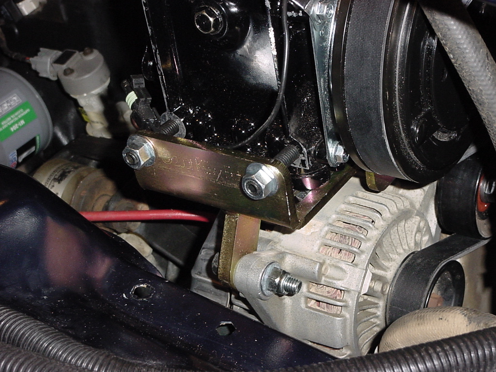
| 22.
Locate the (2) 3/8x2" studs, washers and nuts for the side of
the compressor |
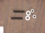 |
| 23. Thread the studs into the side of the York Compressor. a 3/16"
Allen Wrench is used to tighten these studs into the body. |
 |
 |
| 24. Insert the flat washers over the studs and screw the nuts on as shown. |
 |
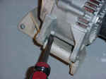
| 25. Now tighten the nuts with a 9/16" Combo wrench evenly to pull
the York compressor to the outside to tighten the serpentine belt.
Once you have the belt tight, tighten the 4 bolts on the bottom side
of the compressor bracket to hold the compressor in place.
Once the lower bolts are tight you can either leave the studs in place
or remove them. I decided to leave them. |
 |
| 26. Reconnect the alternator. The larger battery wire for the alternator
may be to short to reach the alternator on some Jeeps. Try opening
the factory harness and pull the wire out of the loom to extend it.
Mine just reached though I did flip the end over because the tab did
not line up. |
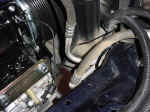
| 27.
Now double check all the bolts and check clearances around the Compressor
and alternator. You may need to bend the aluminum piping for
the A/C lines to clear the hoses away from the compressor. I
didn't have to bend them allot, but I had to bend all of them a little. |
 |
 |
| 28.
Now reinstall the Air Box and hose. |
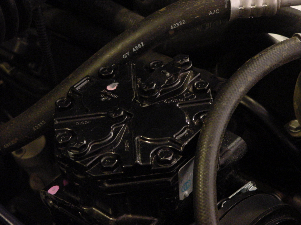
| 29. Now I had the Kilby's suction and discharge fittings so I installed
them. First remove the caps from the suction and discharge ports
on top of the compressor. I did these one at a time so that
I didn't get anything into them while I was working on the other one.
The ports are labeled suction and disch (discharge). |
 |
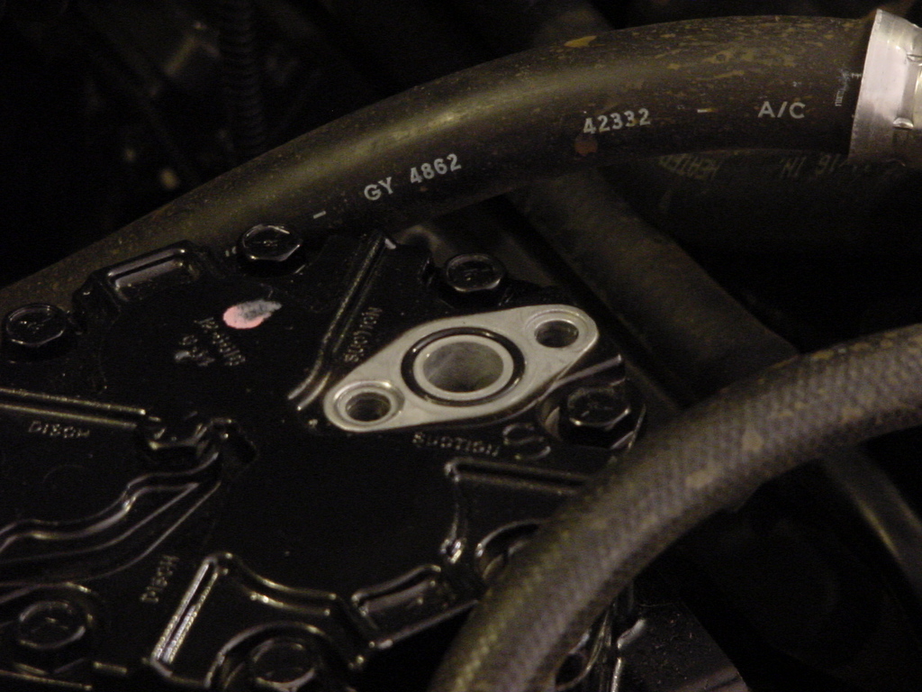
| 30.
I removed the bolts with a 1/2" socket from the cover.
Do this slowly because there may be some pressure built up under the
cap. Once you have the cap off, make certain that the o-ring
is still in its grove. |
 |
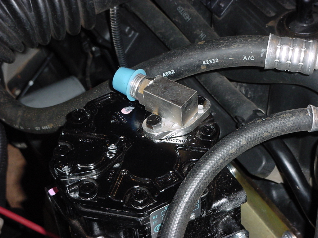
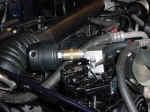
| 31. Install the fitting onto the compressor with the bolts you just removed.
I needed a 1/2" Combo wrench to tighten these down. Make
certain you tighten evenly to properly seat the fitting. Repeat
for the other side. I position both of these towards the rear. |
 |
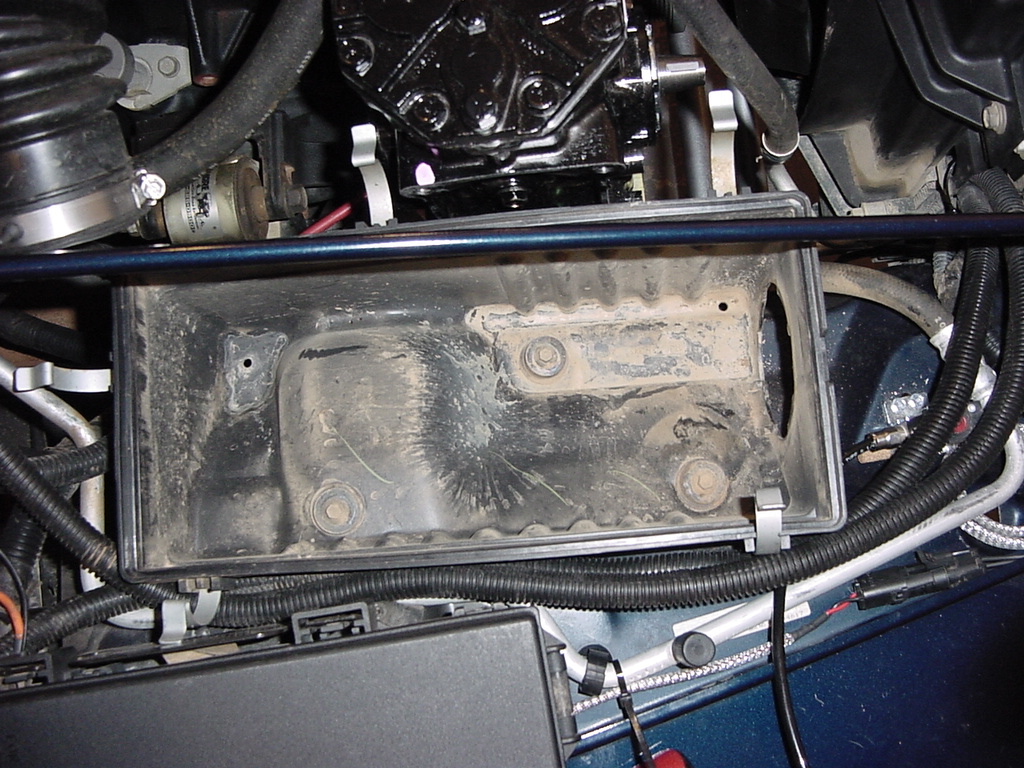
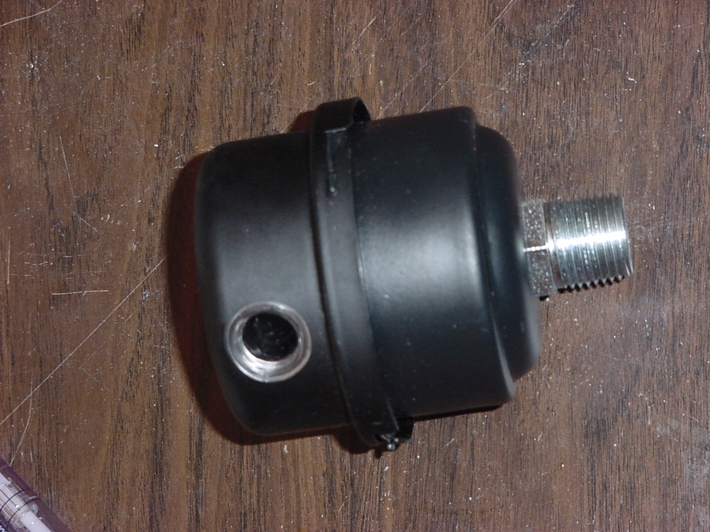
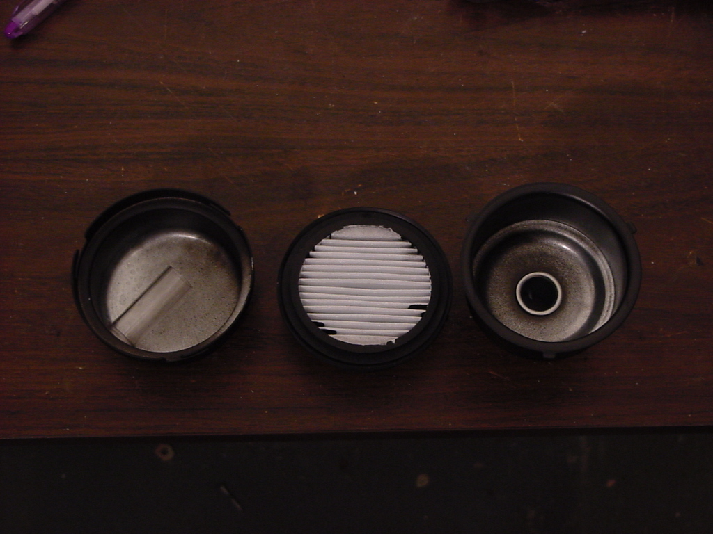
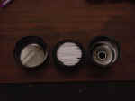
| The
Kilby's air filter. I opened it up just to make certain that
there was nothing inside of it. |
 |
 |
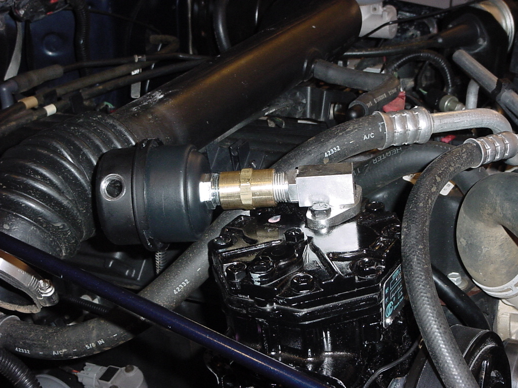
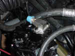
| 32. Now install the air filter and the double female fitting on to the
suction port. It is a tight fit against the engine air inlet
hose. You will need a 7/8" Combo Wrench and a 12"
Adjustable Wrench. |
 |
| 33. Reconnect the battery. |
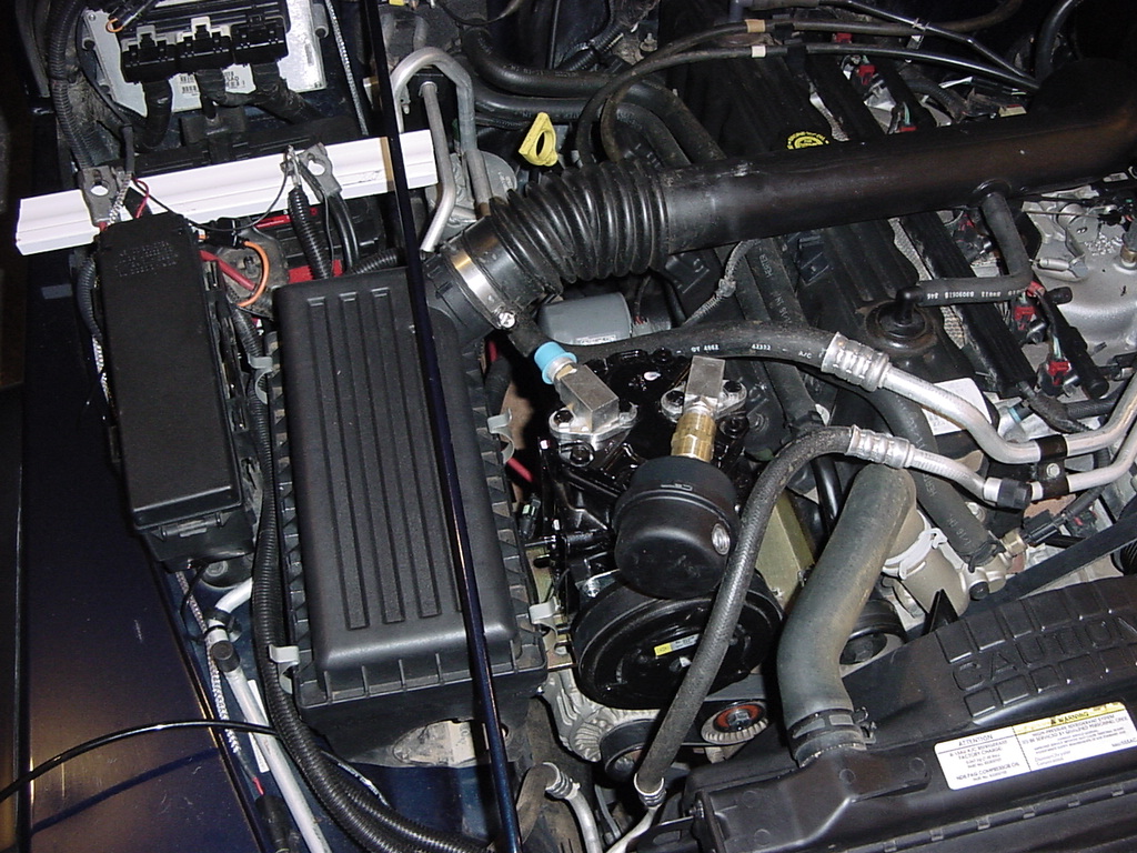
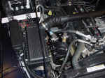
Completed. I
had tried to spin the compressor suction around, but it hits against
the hood.
Note: The compressor is not currently operational, I have not hooked up
power to the clutch yet. I will do that once I get Extreme
Air from Off Road Only installed. |
 |